How to read a pin matrix
Sources down the side. Destinations along the top. A pin where they meet. That's the whole idea, and it's why we put one on every synth we make.
What it is
A pin matrix is a grid. Each row is a source: something that changes over time, like an envelope, an LFO, a joystick axis or the level of an incoming drum loop. Each column is a destination: something that can be changed, like pitch, filter cutoff, a reverb mix or the level of an FM operator.
Where a row crosses a column there's a hole. Push a pin into the hole and the source now modulates that destination. Pull it out and it doesn't. That's it. No cables, no menus, no scrolling through a list of 90 things to find the one you meant.
Where it came from
In 1969 the EMS VCS3 put a 16-by-16 pin matrix on its front panel in place of a nest of patch cords. Every oscillator, filter, envelope and output met every input on one small board, and a patch became something you could photograph, copy onto a card, and hand to a friend. The BBC Radiophonic Workshop ran on them. So did a great deal of the music that still sounds like the future.
The matrix is a classic analog interface. Maybe the classic analog interface. Many older enthusiasts grew up visualising patches that way, and many younger explorers are returning to x/y patching to help visualise complex intermodulation relationships.
Why a grid beats a menu
- You see the whole patch at once. Every connection is a dot in a known place. A menu shows you one connection at a time, in the order the software chose.
- One to many is one row. Want the follower to move cutoff, pan and reverb at once? Three pins in a row. No duplicate slots, no "add modulation" dialogue.
- Many to one is one column. Everything touching filter cutoff is stacked in a single column, so you can read why a sound is doing what it's doing.
- It invites experiment. A pin costs nothing and comes out in a second. Trying "what if the joystick drove the reverb size" is a flick, not a decision.
Building a patch, three pins at a time
- Start with the envelope. Find the Env 1 row. Put a pin under Cutoff. Play a note: the filter opens and closes with the note.
- Add movement. Find the LFO row (or, on Tant and Tonnau, a looping trapezoid envelope). Put a pin under Pitch for vibrato, or under Pan to swing the sound across the stereo field.
- Let the track in. Feed a drum loop into the Sidechain input. Find the Follower 1 row and put pins under Level and Reverb mix. Now the synth ducks and blooms with the kick, and you haven't drawn a single automation lane.
Every pin on a Silicon Antiques synth has its own amount, so a row isn't just on or off: the envelope can open the filter a lot and nudge the pan a little.
What we did with it
Every modulation source, every destination
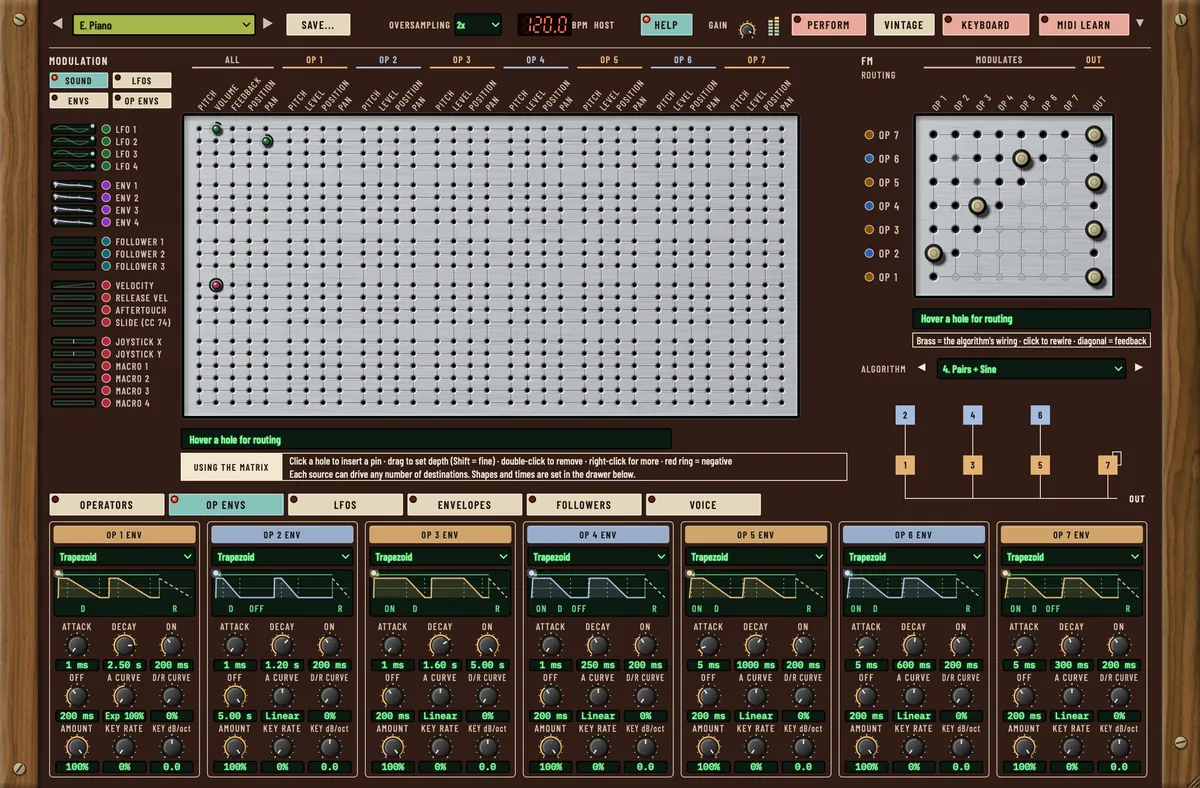
Mellt's matrix is 21 sources by 111 destinations: 2,299 pins. Tonnau's is 23 by 93. Tant's is 22 by 81. Nothing is off-limits: the effects, the envelope stages, the follower times and the other oscillators are all columns.
FM routing on a matrix
Mellt goes one step further and shows the operator routing itself as a pin board. Rows are the operators that modulate; columns are the operators being modulated. Each of Mellt's twelve algorithms is a pattern of pins, and you choose between them by clicking the connection you want. We drew all twelve.
Two matrices, morphed
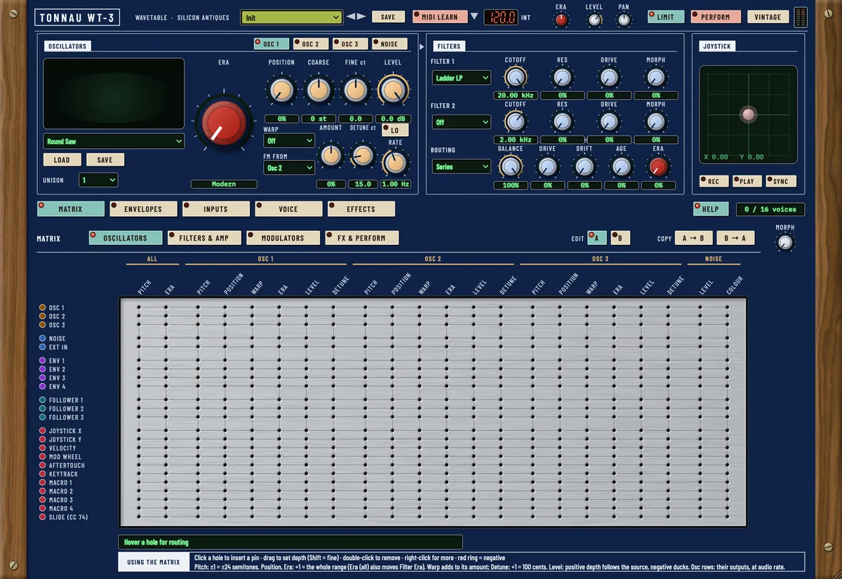
Tant and Tonnau hold two complete pin sets, A and B, and a Matrix Morph control that crossfades between them. Morph is itself a destination, so a macro, a follower or your DAW can sweep one patch into another.
Pins you can automate
On Mellt every pin is a host parameter. Record a pin going in and out and your DAW plays it back.
Try one.
All three Silicon Antiques synths are free for macOS, as AU, VST3 and Standalone. Each has a pin matrix at its heart.